Description
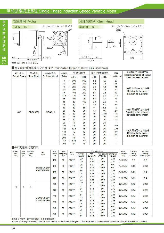
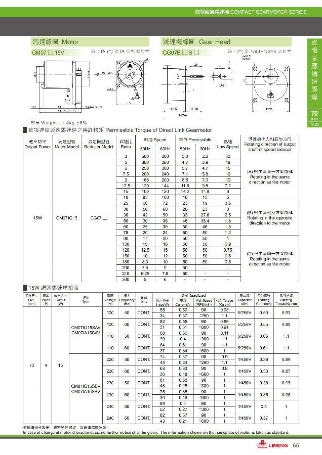
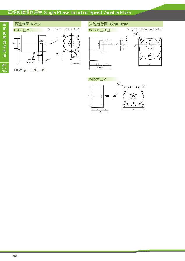
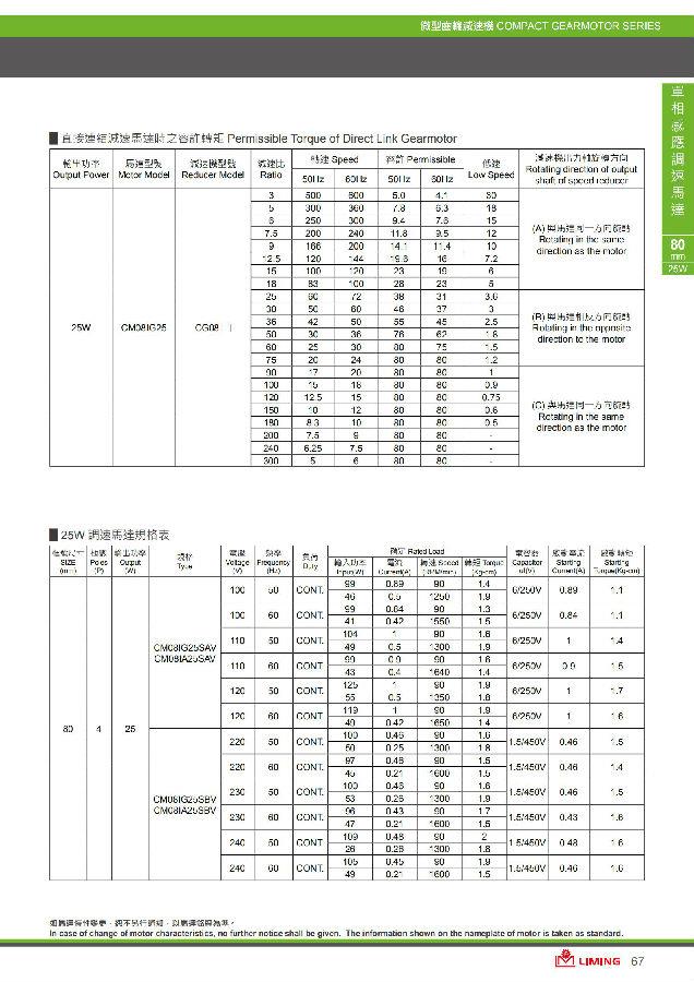
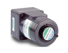
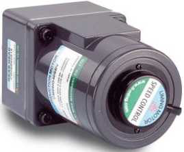
Single-Phase Reversible Speed Variable Motor Features: Suitable for speed adjustment control of single-phase motors.
Single-Phase Reversible Speed Variable Motor
Features: Suitable for speed adjustment control of single-phase motors. (50Hz:90~14000rpm、60Hz:90~1700rpm)
Feature:Applicable for speed adjustment for single-phase motor
(Note:The frequency converter is used for 3-phase motor,to control speed.)
Motor General Specification
Insulation resistance: Measured with a DC500V high resistance meter between the coil and the housing of the motor, and its value is above 100MΩ.
Insulation withstand voltage: 50Hz or 60Hz, 1.5KV is applied between the coil and the shell of the motor for 1 minute without any abnormality. Temperature rise: measured by resistance method after rated continuous rotation of the motor, the temperature rise value is below 80°C.
Insulation class: Type B (130℃)
Protection level: wire type IP20, terminal box type IP54.
Operating temperature: -10℃~+50℃ (capacitor continuous operation motor -10℃~+40℃) (non-freezing state). Operating humidity: 85%below (non-condensing state).
Forced fan (optional): Voltage AC (110V, 220V) provides enhanced heat dissipation when the motor rotates at a low speed.
SCU Assembly Type Controller
Connect the connector of the motor and the controller, connect the AC power at both ends of the controller AC (please confirm whether the power is correct), the LED is green when the switch is switched to the RUN position, and the motor is running at this time, adjust the knob on the controller You can control the speed of the motor speed. Note: The SCUN speed display combined controller uses the same method as the standard combined controller.
SCS Separated Style Controller
Separate controllers are generally used for control in switchboards. The controller body will have a marked wiring diagram. After the wiring between the motor and the controller feet is completed, insert the controller body into the feet, and start the switch when you are ready. Adjust the knob to control the speed of the motor. . Note: Separate controllers have 8 pins and 11 pins according to their functions. The installation dimensions are as shown in the figure below.
